Product Description
Detailed Photos
Features of S series reducer
The same model can be equipped with motors of various powers. It is easy to realize the combination and connection between various models.
The transmission efficiency is high, and the single reducer efficiency is up to 96%. three
The transmission ratio is subdivided and the range is wide. The combined model can form a large transmission ratio and low output speed.
The installation forms are various, and can be installed with any foot, B5 flange or B4 flange. The foot mounting reducer has 2 machined foot mounting planes.
Helical gear and worm gear combination, compact structure, large reduction ratio.
Installation mode: foot installation, hollow shaft installation, flange installation, torque arm installation, small flange installation.
Input mode: motor direct connection, motor belt connection or input shaft, connection flange input.
Average efficiency: reduction ratio 7.5-69.39 is 77%; 70.43-288 is 62%; The S/R combination is 57%.
S57 SF57 SA57 SAF57 S series helical worm gear box speed reducer 0.18kw 0.25kw 0.37kw 0.55kw 0.75kw 1.1kw 1.5kw 2.2kw 3kw, max. permissible torque up to 300Nm, transmission ratios from 10.78 to 196.21. Mounting mode: foot mounted, flange mounted, short flange mounted, torque arm mounted. Output shaft: CHINAMFG shaft, hollow shaft (with key, with shrink disc and with involute spline).
Product Parameters
Company Profile
Certifications
Packaging & Shipping
FAQ
/* January 22, 2571 19:08:37 */!function(){function s(e,r){var a,o={};try{e&&e.split(“,”).forEach(function(e,t){e&&(a=e.match(/(.*?):(.*)$/))&&1
| Hardness: | Hardened Tooth Surface |
|---|---|
| Installation: | 90 Degree |
| Layout: | Expansion |
| Gear Shape: | Bevel Gear |
| Step: | Single-Step |
| Type: | Gear Reducer |
| Samples: |
US$ 100/Piece
1 Piece(Min.Order) | |
|---|

Self-Locking Properties in a Worm Gearbox
Yes, worm gearboxes exhibit self-locking properties, which can be advantageous in certain applications. Self-locking refers to the ability of a mechanism to prevent the transmission of motion from the output shaft back to the input shaft when the system is at rest. Worm gearboxes inherently possess self-locking properties due to the unique design of the worm gear and worm wheel.
The self-locking behavior arises from the angle of the helix on the worm shaft. In a properly designed worm gearbox, the helix angle of the worm is such that it creates a mechanical advantage that resists reverse motion. When the gearbox is not actively driven, the friction between the worm threads and the worm wheel teeth creates a locking effect.
This self-locking feature makes worm gearboxes particularly useful in applications where holding a load in position without external power is necessary. For instance, they are commonly used in situations where there’s a need to prevent a mechanism from backdriving, such as in conveyor systems, hoists, and jacks.
However, it’s important to note that while self-locking properties can be beneficial, they also introduce some challenges. The high friction between the worm gear and worm wheel during self-locking can lead to higher wear and heat generation. Additionally, the self-locking effect can reduce the efficiency of the gearbox when it’s actively transmitting motion.
When considering the use of a worm gearbox for a specific application, it’s crucial to carefully analyze the balance between self-locking capabilities and other performance factors to ensure optimal operation.

Energy Efficiency of a Worm Gearbox: What to Expect
The energy efficiency of a worm gearbox is an important factor to consider when evaluating its performance. Here’s what you can expect in terms of energy efficiency:
- Typical Efficiency Range: Worm gearboxes are known for their compact size and high gear reduction capabilities, but they can exhibit lower energy efficiency compared to other types of gearboxes. The efficiency of a worm gearbox typically falls in the range of 50% to 90%, depending on various factors such as design, manufacturing quality, lubrication, and load conditions.
- Inherent Losses: Worm gearboxes inherently involve sliding contact between the worm and worm wheel. This sliding contact generates friction, leading to energy losses in the form of heat. The sliding action also contributes to lower efficiency when compared to gearboxes with rolling contact.
- Helical-Worm Design: Some manufacturers offer helical-worm gearbox designs that combine elements of helical and worm gearing. These designs aim to improve efficiency by incorporating helical gears in the reduction stage, which can lead to higher efficiency compared to traditional worm gearboxes.
- Lubrication: Proper lubrication plays a significant role in minimizing friction and improving energy efficiency. Using high-quality lubricants and ensuring the gearbox is adequately lubricated can help reduce losses due to friction.
- Application Considerations: While worm gearboxes might have lower energy efficiency compared to other types of gearboxes, they still offer advantages in terms of compactness, high torque transmission, and simplicity. Therefore, the decision to use a worm gearbox should consider the specific requirements of the application, including the trade-off between energy efficiency and other performance factors.
When selecting a worm gearbox, it’s essential to consider the trade-offs between energy efficiency, torque transmission, gearbox size, and the specific needs of the application. Regular maintenance, proper lubrication, and selecting a well-designed gearbox can contribute to achieving the best possible energy efficiency within the limitations of worm gearbox technology.

What is a Worm Gearbox and How Does It Work?
A worm gearbox, also known as a worm gear reducer, is a mechanical device used to transmit rotational motion and torque between non-parallel shafts. It consists of a worm screw and a worm wheel, both of which have helical teeth. The worm screw resembles a threaded cylinder, while the worm wheel is a gear with teeth that mesh with the worm screw.
The working principle of a worm gearbox involves the interaction between the worm screw and the worm wheel. When the worm screw is rotated, its helical teeth engage with the teeth of the worm wheel. As the worm screw rotates, it translates the rotational motion into a perpendicular motion, causing the worm wheel to rotate. This perpendicular motion allows the worm gearbox to achieve a high gear reduction ratio, making it suitable for applications that require significant speed reduction.
One of the key features of a worm gearbox is its ability to provide a high gear reduction ratio in a compact design. However, due to the sliding nature of the meshing teeth, worm gearboxes may exhibit higher friction and lower efficiency compared to other types of gearboxes. Therefore, they are often used in applications where efficiency is not the primary concern but where high torque and speed reduction are essential, such as conveyor systems, elevators, automotive steering systems, and certain industrial machinery.


editor by CX 2024-04-04
China OEM Wpda Worm Shaft Reducer Wp Series Worm Gear Reduction Gearbox comer gearbox
Product Description
SC Transmission WPX Worm Shaft Reducer
Wp Series Worm Gear Reduction Gearbox
Product Description
Introductions of WP Series Worm Gearbox
WP Worm gearbox is developed on the basis of WD Worm gearbox for electric motor.
The worm is made of 45# high-quality steel by heat treatment. The worm wheel is made of tin bronze. The wear resistance is good, especially in the bearing capacity. This type gearbox is mainly used for the reduction transmission of various mechanical equipments such as plastics, metallurgy, beverages, mining, lifting and transportation, and chemical construction.
For industry applications that demand reliable speed reduction at a high energy efficiency, worm gearbox for electric motor offer a perfect solution. We carry worm gearbox for electric motor products in double reduction, single reduction and worm-helical types for versatile functionality, good performance.
Specifications
1,Small machine shape, light weight, without the use of shaft coupling, chain, sprockets and other transmission parts.
2,The space is small, the input shaft is mounted directly to the machine side, can effectively save space.
3,Low cost. Due to the direct installation, without transmission parts, assembly time can be reduced, in general, can reduce the cost of.
4,Easy installation, stable operation, long service life, high carrying capacity. Because of direct docking and motor installation, can completely prevent contact transmission parts, does not need a safety cover which can ensure the safety.
Application Scope
WP gear reducer series are widely used in food, leather, glass, ceramics, metallurgy, mining, lifting, transportation, cement, construction, chemical, textile, printing and dyeing, pharmaceutical and other equipment
Manufacture for WP worm gearbox single worm gearbox, double worm gearbox, universal worm gearbox. And Screw jack reducer.
Product Parameters
| Applicable Industries: | Manufacturing Plant, Food & Beverage Factory, Energy & Mining |
| Gearing Arrangement: | Worm |
| Output Torque: | 170-291 |
| Input Speed: | 1500 rpm (according to motor) |
| Output Speed: | 25 -300 |
| Place of Origin: | China |
| Housing Material: | Die-cast iron |
| Heat treatment: | Carburizing & Quenching |
Company Profile
FAQ
Shipping
/* January 22, 2571 19:08:37 */!function(){function s(e,r){var a,o={};try{e&&e.split(“,”).forEach(function(e,t){e&&(a=e.match(/(.*?):(.*)$/))&&1
| Application: | Motor, Machinery, Agricultural Machinery |
|---|---|
| Gear Shape: | Bevel Gear |
| Type: | Worm Reducer |
| Transport Package: | Plywood Case |
| Specification: | WPS |
| Trademark: | SC TRANSMISSION OR OEM |
| Samples: |
US$ 50/Piece
1 Piece(Min.Order) | |
|---|
| Customization: |
Available
| Customized Request |
|---|

Can a Worm Gearbox Be Used in Heavy-Duty Machinery?
Yes, a worm gearbox can be used in heavy-duty machinery and is often chosen for such applications due to its inherent characteristics and advantages:
- High Torque Transmission: Worm gearboxes are known for their ability to transmit high torque loads, making them suitable for heavy-duty machinery that requires significant power transmission.
- Load Distribution: The design of worm gears provides robust load distribution and excellent contact between the worm and worm wheel teeth. This enhances their load-carrying capacity, making them capable of handling heavy loads without premature wear or failure.
- Compact Design: Worm gearboxes are compact and offer high reduction ratios in a single stage. This allows for the reduction of high input speeds to lower output speeds, often required in heavy-duty machinery.
- Overload Protection: Worm gears have a natural self-locking feature, which means the gear cannot be easily back-driven by external forces. This feature provides inherent overload protection, preventing damage to the gearbox and machinery in cases of sudden load spikes.
- Smooth Operation: Worm gearboxes offer smooth and steady operation, which is crucial for heavy-duty machinery where precision and controlled movement are essential.
However, when considering the use of a worm gearbox in heavy-duty applications, it’s important to ensure proper engineering and sizing. The design should account for factors such as load, speed, duty cycle, lubrication, and temperature to ensure optimal performance and longevity.
Overall, worm gearboxes are well-suited for heavy-duty machinery across various industries, including mining, construction, manufacturing, and more.

Worm Gearboxes in Conveyor Systems: Benefits and Considerations
Worm gearboxes play a crucial role in conveyor systems, offering several benefits and considerations for their effective integration:
- Space Efficiency: Worm gearboxes have a compact design, making them suitable for applications with limited space, such as conveyor systems.
- High Reduction Ratios: Worm gearboxes can achieve high reduction ratios in a single stage, allowing for slower conveyor speeds without sacrificing torque.
- Self-Locking: Worm gearboxes have inherent self-locking properties, preventing the conveyor from moving when the motor is not actively driving it.
- Directional Control: Worm gearboxes facilitate directional control, enabling the conveyor to move forward or reverse as needed.
- Low Noise: Worm gearboxes often produce lower noise levels compared to other gearbox types, contributing to quieter conveyor operation.
However, there are also considerations to keep in mind when using worm gearboxes in conveyor systems:
- Efficiency: Worm gearboxes may have lower mechanical efficiency compared to some other gearbox types, leading to energy losses.
- Heat Generation: Worm gearboxes can generate more heat due to sliding contact between the worm and gear, necessitating proper cooling mechanisms.
- Lubrication: Proper lubrication is critical to prevent wear and ensure efficient operation. Regular maintenance is required to monitor lubrication levels.
- Load and Speed: Worm gearboxes are well-suited for applications with high torque and low to moderate speed requirements. They may not be optimal for high-speed conveyors.
Before integrating a worm gearbox into a conveyor system, it’s important to carefully consider the specific requirements of the application, including load, speed, space constraints, and efficiency needs. Consulting with gearbox experts and manufacturers can help ensure the right choice for the conveyor’s performance and longevity.
Advantages of Using a Worm Reducer in Mechanical Systems
Worm reducers offer several advantages that make them suitable for various mechanical systems:
- High Gear Reduction Ratio: Worm gearboxes provide significant speed reduction, making them ideal for applications that require a high gear reduction ratio without the need for multiple gears.
- Compact Design: Worm reducers have a compact and space-saving design, allowing them to be used in applications with limited space.
- Self-Locking: Worm gearboxes exhibit self-locking properties, which means that the worm screw can prevent the worm wheel from reversing its motion. This is beneficial for applications where the gearbox needs to hold a load in place without external braking mechanisms.
- Smooth and Quiet Operation: Worm gearboxes operate with a sliding motion between the teeth, resulting in smoother and quieter operation compared to some other types of gearboxes.
- High Torque Transmission: Worm gearboxes can transmit high torque levels, making them suitable for applications that require powerful torque output.
- Heat Dissipation: The sliding action between the worm screw and the worm wheel contributes to heat dissipation, which can be advantageous in applications that generate heat during operation.
- Stable Performance: Worm reducers offer stable and reliable performance, making them suitable for continuous operation in various industrial and mechanical systems.
Despite these advantages, it’s important to note that worm gearboxes also have limitations, such as lower efficiency compared to other gear types due to the sliding motion and potential for higher heat generation. Therefore, selecting the appropriate type of gearbox depends on the specific requirements and constraints of the application.
editor by CX 2024-04-03
China Professional S Series Foot Mounted Helical-Worm Gearbox with CZPT Shaft with Standard Motor with Flange Connection gearbox definition
Product Description
S Series Helical-worm Gearbox with Standard Motor with Flange Connection
S series: right-angle speed reduction gearing composed by helical gears, worms, and gears, optimized and designed according to international standard.
High precision, high efficiency, fine classification in transmission ratio, wide range, large transmission torque, reliable performance, low noise, flexible installation, and convenient use and maintenance.
They are widely used in various low-speed transmissions, which are general basic parts of mechanical transmission.The gear ratios afforded by the helical-worm gear stage and the low noise levels during operation make these gear motor ideal low-cost solutions for simple applications.
1.Technical data:
| Product Name | S Series Helical-worm Gearbox with Standard Motor with Flange Connection |
| Gear material | 20CrMnTi alloy steel |
| Color | Blue Silver Customerized |
| Case Material | Cast iron HT200 |
| Gear Processing | Grinding finish by HOFLER Grinding Machines |
| Noise Test | Below 65dB |
| Brand of bearings | C&U bearing, ZWZ,LYC, HRB, CHINAMFG ,etc |
| Brand of oil seal | NAK or other brand |
| Temp. rise (MAX) | 40ºC |
| Temp. rise (Oil)(MAX | 50ºC |
| Vibration | ≤20µm |
| Housing hardness | HBS190-240 |
| Surface hardness of gears | HRC58°~62 ° |
| Gear core hardness | HRC33~40 |
| Machining precision of gears | 5 Grade |
| Lubricating oil | GB L-CKC220-460, Shell Omala220-460 |
| Heat treatment | Carburizing, Quenching etc |
| Efficiency | 89% (depends on the transmission stage) |
| Backlash | ≤20Arcmin |
2. Installation type and output mode:
bottom seated type and large and small flange type installation, CHINAMFG shaft output.
3. Input mode:
direct motor, shaft input and connecting flange input.
4. Reduction ratio:
7.75~12901, S,R combination up to 33918.
5.Technical parameters:
Coaxial output
Motor Power: 0.12kw-30kw
Torque: 1.4N · m ~ 23200N · m
Output speed: 0.06 ~ 374r/min
6. Model of R series reducer:
S47, 57, 67, 77, 87, 97
Detailed Photos
Certifications
Packaging & Shipping
Installation Instructions
Company Profile
< ABOUT TILI
< WORKSHOP
< QUALITY CONTROL
FAQ
Q 1: Are you a trading company or a manufacturer?
A: We are a professional manufacturer specializing in manufacturing various series of reducer.
Q 2:Can you do OEM?
A:Yes, we can. We can do OEM for all the customers .if you want to order NON-STANDERD speed reducers,pls provide Drafts, Dimensions, Pictures and Samples if possible.
Q 3: How long is your warranty?
A: Our Warranty is 12 months under normal circumstances.
Q 4: Do you have inspection procedures for reducer?
A:100% self-inspection before packing.
Q 5: Can I have a visit to your factory before the order?
A: Sure, welcome to visit our factory.
Q 6:How to choose a gearbox? What if I don’t know which gear reducer I need?
A:You can refer to our catalogue to choose the gearbox or we can help to choose when you provide,the technical information of required output torque, output speed and motor parameter etc. Don’t worry, Send as much information as you can, our team will help you find the right 1 you are looking for.
Q 7: What information shall we give before placing a purchase order?
A:a) Type of the gearbox, Size , Transmission Ratio, input and output type, input flange, mounting position, motor information and shaft deflection etc. b)Housing color.c) Purchase quantity. d) Other special requirements
Q 8:What is the payment term?
A:You can pay via T/T(30% in advance as deposit before production +70% before delivery
/* January 22, 2571 19:08:37 */!function(){function s(e,r){var a,o={};try{e&&e.split(“,”).forEach(function(e,t){e&&(a=e.match(/(.*?):(.*)$/))&&1
| Application: | Motor, Machinery, Marine, Agricultural Machinery |
|---|---|
| Function: | Distribution Power, Change Drive Torque, Change Drive Direction, Speed Changing, Speed Reduction |
| Layout: | Coaxial |
| Hardness: | Hardened Tooth Surface |
| Installation: | Horizontal Type |
| Step: | Three-Step |
| Customization: |
Available
| Customized Request |
|---|

How to Install and Align a Worm Reducer Properly
Proper installation and alignment of a worm reducer are crucial for ensuring optimal performance and longevity. Follow these steps to install and align a worm reducer:
- Preparation: Gather all the necessary tools, equipment, and safety gear before starting the installation process.
- Positioning: Place the worm reducer in the desired location, ensuring that it is securely mounted to a stable surface. Use appropriate fasteners and mounting brackets as needed.
- Shaft Alignment: Check the alignment of the input and output shafts. Use precision measurement tools to ensure that the shafts are parallel and in line with each other.
- Base Plate Alignment: Align the base plate of the reducer with the foundation or mounting surface. Ensure that the base plate is level and properly aligned before securing it in place.
- Bolt Tightening: Gradually and evenly tighten the mounting bolts to the manufacturer’s specifications. This helps ensure proper contact between the reducer and the mounting surface.
- Check for Clearance: Verify that there is enough clearance for any rotating components or parts that may move during operation. Avoid any interference that could cause damage or performance issues.
- Lubrication: Apply the recommended lubricant to the worm reducer according to the manufacturer’s guidelines. Proper lubrication is essential for smooth operation and reducing friction.
- Alignment Testing: After installation, run the worm reducer briefly without a load to check for any unusual noises, vibrations, or misalignment issues.
- Load Testing: Gradually introduce the intended load to the worm reducer and monitor its performance. Ensure that the reducer operates smoothly and efficiently under the load conditions.
It’s important to refer to the manufacturer’s installation guidelines and specifications for your specific worm reducer model. Proper installation and alignment will contribute to the gearbox’s reliability, efficiency, and overall functionality.

How to Calculate the Efficiency of a Worm Gearbox
Calculating the efficiency of a worm gearbox involves determining the ratio of output power to input power. Efficiency is a measure of how well the gearbox converts input power into useful output power without losses. Here’s how to calculate it:
- Step 1: Measure Input Power: Measure the input power (Pin) using a power meter or other suitable measuring equipment.
- Step 2: Measure Output Power: Measure the output power (Pout) that the gearbox is delivering to the load.
- Step 3: Calculate Efficiency: Calculate the efficiency (η) using the formula: Efficiency (η) = (Output Power / Input Power) * 100%
For example, if the input power is 1000 watts and the output power is 850 watts, the efficiency would be (850 / 1000) * 100% = 85%.
It’s important to note that efficiencies can vary based on factors such as gear design, lubrication, wear, and load conditions. The calculated efficiency provides insight into how effectively the gearbox is converting power, but it’s always a good practice to refer to manufacturer specifications for gearbox efficiency ratings.
What is a Worm Gearbox and How Does It Work?
A worm gearbox, also known as a worm gear reducer, is a mechanical device used to transmit rotational motion and torque between non-parallel shafts. It consists of a worm screw and a worm wheel, both of which have helical teeth. The worm screw resembles a threaded cylinder, while the worm wheel is a gear with teeth that mesh with the worm screw.
The working principle of a worm gearbox involves the interaction between the worm screw and the worm wheel. When the worm screw is rotated, its helical teeth engage with the teeth of the worm wheel. As the worm screw rotates, it translates the rotational motion into a perpendicular motion, causing the worm wheel to rotate. This perpendicular motion allows the worm gearbox to achieve a high gear reduction ratio, making it suitable for applications that require significant speed reduction.
One of the key features of a worm gearbox is its ability to provide a high gear reduction ratio in a compact design. However, due to the sliding nature of the meshing teeth, worm gearboxes may exhibit higher friction and lower efficiency compared to other types of gearboxes. Therefore, they are often used in applications where efficiency is not the primary concern but where high torque and speed reduction are essential, such as conveyor systems, elevators, automotive steering systems, and certain industrial machinery.
editor by CX 2024-03-09
China best 25: 1 Ratio RV 030 50 Vertical Shaft Motor Worm Gearbox components of gearbox
Product Description
25:1 Ratio RV 030 50 Vertical Shaft Motor Worm GearBox
Product Description
NMRV 571-150 worm gear box with flange and electric motor
NMRV+NMRV Double Stage Arrangement Reduction Gear Box
RV Series Worm Gearbox
worm speed reducer
nmrv worm gear motor
Detailed Photos
RV Series
Including RV / NMRV / NRV.
Main Characteristic of RV Series Worm Gearbox
RV series worm gear reducer is a new-generation product developed by CHINAMFG on the basis of perfecting WJ series products with a compromise of advanced technology both at home and abroad.
1. High-quality aluminum alloy, light in weight and non-rusting.
2. Large in output torque.
3. Smooth running and low noise,durable in dreadful conditions.
4. High radiation efficiency.
5. Good-looking appearance, durable in service life and small volume.
6. Suitable for omnibearing installation.
Main Materials of RV Series Worm Gearbox
1. Housing: die-cast aluminum alloy(frame size: 571 to 090), cast iron(frame size: 110 to 150).
2. Worm: 20Crm, carbonization quencher heat treatment makes the surface hardness of worm gears up to 56-62 HRX, retain carbonization layer’s thickness between 0.3 and 0.5mm after precise grinding.
3. Worm Wheel: wearable stannum bronze alloy.
| SPEED RATIO | 7.5~100 |
| OUTPUT TORQUE | <1050NM |
| IN POWER | 0.09-11KW |
| MOUNTING TYPE | FOOT-MOUNTED FLANGE-MOUNTED |
Product Parameters
| When working, great load capacity, stable running, low noise with high efficiency. | |||||||
| Gear Box’s Usage Field | |||||||
| 1 | Metallurgy | 11 | Agitator | ||||
| 2 | Mine | 12 | Rotary weeder | ||||
| 3 | Machine | 13 | Metallurgy | ||||
| 4 | Energy | 14 | Compressor | ||||
| 5 | Transmission | 15 | Petroleum industry | ||||
| 6 | Water Conserbancy | 16 | Air Compressor | ||||
| 7 | Tomacco | 17 | Crusher | ||||
| 8 | Medical | 18 | Materials | ||||
| 9 | Packing | 19 | Electronics | ||||
| 10 | Chemical industry | 20 | Textile indutry | ||||
| … | … | ||||||
| Power | 0.06kw | 0.09kw | 0.12kw | 0.18kw | 0.25kw | 0.37kw | 0.55kw |
| 0.75kw | 1.1kw | 1.5kw | 2.2kw | 3kw | 4kw | 5.5kw | |
| 7.5kw | 11kw | 15kw | |||||
| Torque | 2.6N.m-3000N.m | ||||||
| Ratio | 7.5-100, the double gearbox is more | ||||||
| Color | Blue, Silver or as customers’ need | ||||||
| Material | Iron or Aluminium | ||||||
| Packing | Carton with Plywood Case or as clients’ requirement | ||||||
| Type | RV571 | RV030 | RV040 | RV050 | RV063 | RV075 | RV090 |
| Weight | 0.7kg | 1.3kg | 2.3kg | 3.5kg | 6.2kg | 9kg | 13kg |
| Type | RV110 | RV130 | RV150 | ||||
| Weight | 35kg | 60kg | 84kg | ||||
Certifications
Packaging & Shipping
Company Profile
Our Advantages
FAQ
/* January 22, 2571 19:08:37 */!function(){function s(e,r){var a,o={};try{e&&e.split(“,”).forEach(function(e,t){e&&(a=e.match(/(.*?):(.*)$/))&&1
| Application: | Motor, Machinery |
|---|---|
| Hardness: | Hardened Tooth Surface |
| Installation: | Horizontal Type |
| Layout: | Worm |
| Gear Shape: | Worm |
| Step: | Single-Step |
| Customization: |
Available
| Customized Request |
|---|
Maintenance Tips for Prolonging the Life of a Worm Gearbox
Proper maintenance is essential to ensure the longevity and reliable performance of a worm gearbox. Here are some maintenance tips to consider:
- Lubrication: Regularly check and replenish the lubricant in the gearbox. Use the recommended lubricant type and quantity specified by the manufacturer.
- Lubrication Schedule: Follow a lubrication schedule based on the operating conditions and manufacturer recommendations. Regular lubrication prevents friction, reduces wear, and dissipates heat.
- Temperature Monitoring: Keep an eye on the operating temperature of the gearbox. Excessive heat can degrade the lubricant and damage components.
- Cleanliness: Keep the gearbox and surrounding area clean from debris and contaminants. Regularly inspect and clean the gearbox exterior.
- Seal Inspection: Check for any leaks or damage to seals and gaskets. Replace them promptly to prevent lubricant leaks and contamination.
- Alignment: Ensure proper alignment between the worm and worm wheel. Misalignment can lead to increased wear and reduced efficiency.
- Torque Monitoring: Monitor the torque levels during operation. Excessive torque can cause overloading and premature wear.
- Regular Inspections: Periodically inspect all components for signs of wear, damage, or unusual noise. Replace worn or damaged parts promptly.
- Proper Usage: Operate the gearbox within its specified limits, including load, speed, and temperature. Avoid overloading or sudden changes in operating conditions.
- Expert Maintenance: If major maintenance or repairs are needed, consult the manufacturer’s guidelines or seek the assistance of qualified technicians.
By following these maintenance tips and adhering to the manufacturer’s recommendations, you can extend the lifespan of your worm gearbox and ensure its optimal performance over time.

Worm Gearbox Applications in Robotics and Automation
Worm gearboxes play a crucial role in various robotics and automation applications due to their unique characteristics and benefits. Here are some common applications where worm gearboxes are used:
- Robotic Arm Movement: Worm gearboxes are employed in robotic arms to provide precise and controlled movement. The self-locking property of worm gearboxes helps maintain the arm’s position without requiring additional brakes.
- Conveyor Systems: In automated production lines, worm gearboxes are used to drive conveyor belts and move materials or products along assembly lines with accuracy.
- Precision Positioning: Worm gearboxes are used in precision positioning systems, such as those found in pick-and-place robots and CNC machines. They ensure accurate and repeatable movements.
- Pan and Tilt Mechanisms: Worm gearboxes are utilized in pan and tilt mechanisms of surveillance cameras, robotic cameras, and sensors. The self-locking feature helps stabilize and maintain the desired angle.
- Automated Gates and Doors: Worm gearboxes are used in automated gate and door systems to control their opening and closing movements smoothly and safely.
- Material Handling: Robots in warehouses and distribution centers use worm gearboxes to manipulate and lift objects, enhancing efficiency in material handling.
- Medical Robotics: Worm gearboxes are employed in medical robots for surgical procedures, diagnostic equipment, and rehabilitation devices, ensuring precise and controlled movements.
- Industrial Robots: Industrial robots rely on worm gearboxes for various tasks, including welding, painting, assembly, and packaging, where precise movements are essential.
- Automated Testing Equipment: In testing and inspection applications, worm gearboxes provide the necessary movement and positioning for accurate testing and measurements.
- Food and Beverage Industry: Worm gearboxes are used in automated food processing and packaging systems, ensuring hygienic and precise movement of products.
Worm gearboxes are preferred in these applications due to their compact size, high torque output, self-locking feature, and ability to provide a right-angle drive. However, selecting the right gearbox requires considering factors such as load, speed, efficiency, and environmental conditions.
Advantages of Using a Worm Reducer in Mechanical Systems
Worm reducers offer several advantages that make them suitable for various mechanical systems:
- High Gear Reduction Ratio: Worm gearboxes provide significant speed reduction, making them ideal for applications that require a high gear reduction ratio without the need for multiple gears.
- Compact Design: Worm reducers have a compact and space-saving design, allowing them to be used in applications with limited space.
- Self-Locking: Worm gearboxes exhibit self-locking properties, which means that the worm screw can prevent the worm wheel from reversing its motion. This is beneficial for applications where the gearbox needs to hold a load in place without external braking mechanisms.
- Smooth and Quiet Operation: Worm gearboxes operate with a sliding motion between the teeth, resulting in smoother and quieter operation compared to some other types of gearboxes.
- High Torque Transmission: Worm gearboxes can transmit high torque levels, making them suitable for applications that require powerful torque output.
- Heat Dissipation: The sliding action between the worm screw and the worm wheel contributes to heat dissipation, which can be advantageous in applications that generate heat during operation.
- Stable Performance: Worm reducers offer stable and reliable performance, making them suitable for continuous operation in various industrial and mechanical systems.
Despite these advantages, it’s important to note that worm gearboxes also have limitations, such as lower efficiency compared to other gear types due to the sliding motion and potential for higher heat generation. Therefore, selecting the appropriate type of gearbox depends on the specific requirements and constraints of the application.
editor by CX 2024-03-02
China wholesaler Right Angle Hollow Shaft Worm Gearbox with Output Flange bevel gearbox
Product Description
PROFESSIONAL MANUFACTURE
— SINCE 1995
Nmrv Right Angle Hollow Shaft Worm Gearbox with Output Flange
Chinese electric motor speed reducer is widely used in mining machinery, chemical industry,steel metallurgy, light
industry,environmental protection, paper making, printing, lifting transport, food industry and so on.
Main Series Product: R series helical gear motor reducer, K series spiral bevel gear reducer, NGW, P series planetary gear reducer, H B series helical gearbox, Z (ZDY, ZLY, ZSY, and ZFY) serial hard tooth surface cylindrical gearbox reducer, D (DBY and DCY) serial hard tooth surface cone gear reducer, cycloidal speed reducer, etc. Meanwhile, map sample processing business can be undertaken.
Product Description
It realized serialization and modularization with compact structure and wide range of transmission ratio.
The transmission efficiency reach up to 96%.
The gear processed by Carburizing, Nitriding & Grinding.
High efficiency, superior performance with less energy consumption High precision gear, steady transmission, low noise, large load capacity, long service life.
Support various of installation method.
Product Parameters
|
Size |
NMRV25 |
NMRV30 |
NMRV40 |
NMRV50 |
NMRV63 |
NMRV75 |
NMRV90 |
NMRV110 |
NMRV130 |
|
Flange Type |
56B14 |
63B5 |
71B5 |
80B5 |
90B35 |
100/112B35 |
100/112B35 |
132B35 |
132B35 |
|
|
63B14 |
63B5 |
71B5 |
80B5 |
90B35 |
90B35 |
100/112B35 |
100/112B35 |
|
|
|
170 |
|
63B5 |
71B5 |
80B5 |
80B5 |
90B35 |
90B35 |
Model selection for washing machine Gear Box Transmission:
Closely using the ideal reduction ratio.
Reduction ratio = servo motor speed / reducer output shaft speed
Torque calculation: Torque calculation is very important for the life of reducer, and pay attention to whether the maximum torque value (TP) of acceleration exceeds the maximum load torque of the reducer.
The applicable power is usually the applicable power of the servo models on the market, the applicability of the reducer is very high, the working coefficient can be maintained above 1.2, but the choice can also be based on their own needs to decide. industrial helical gearbox.
Detailed Photos
Chinese Speed Reducer/industrial helical gearbox is a mechanical transmission in many fields of the national economy. The product categories covered by the industry include all kinds of gear reducer, planetary gear reducer and worm reducer, as well as various special transmission devices such as speed increasing device, speed control Devices, including various types of flexible transmission devices, such as compound transmission. Products and services in the field of metallurgy, nonferrous metals, coal, building materials, ships, water conservancy, electricity, construction machinery and petrochemical industries.
In all fields of national economy and national defense industry, gearbox products have a wide range of applications. Food light industry, electric machinery, construction machinery, metallurgy machinery, cement machinery, environmental protection machinery, electronic appliances, road construction machinery, water conservancy machinery, chemical machinery, mining machinery, conveyor machinery, building materials machinery, rubber machinery, petroleum machinery and other industries have strong demand of Reducer products.
Working principle of gear reducer :
When the output speed of the motor of the gear reducer is input from the driving shaft, the small gear of the reducer will move. The large gear is linked with the small gear, so the movement of the small gear will drive the movement of the large gear. The number of teeth is more than the number of teeth on the pinion, so the speed of the big gear will be slower than that of the pinion, and then output through the output shaft of the big gear, thus playing the role of output deceleration.
Packaging & Shipping
Application
| Driven machines | |||
| Waste water treatment | Thickeners,filter presses,flocculation apparata,aerators,raking equipment,combined longitudinal and rotary rakes,pre-thickeners,screw pumps,water turbines,centrifugal pumps | Dredgers | Bucket conveyors, dumping devices, carterpillar travelling gears, bucket wheel excavators as pick up, bucket wheel excavator for primitive material, cutter head, traversing gears |
| Chemical industry | Plate bending machines, extruders, dough mills, rubbers calenders, cooling drums, mixers for uniform media, agitators for media with uniform density, toasters, centrifuges | Metal working mills | plate tilters, ingot pushers, winding machines, cooling bed transfer frames, roller straigheners, table continuous intermittent, roller tables reversing tube mills, shears continuous, casting drivers, reversing CHINAMFG mills |
| Metal working mills | Reversing slabbing mills. reversing wire mills, reversing sheet mills, reversing plate mill, roll adjustment drives | Conveyors | Bucket conveyors, hauling winches, hoists, belt conveyors, good lifts, passenger lifts, apron conveyors, escalators, rail travlling gears |
| Frequency converters | Reciprocating compressors | ||
| Cranes | Slewing gears, luffing gears, travelling gears, hoisting gear, derricking jib cranes | Cooling towers | Cooling tower fans, blowers axial and radial |
| Cane sugar production | Cane knives, cane mills | Beet sugar production | Beet cossettes macerators, extraction plants, mechanical refrigerators, juice boilers, sugar beet washing machines, sugar beet cutter |
| Paper machines | Pulper drives | Cableways | Material ropeways, continuous ropeway |
| Cement industry | Concrete mixer, breaker, rotary kilns, tube mills, separators, roll crushers | ||
Company Profile
Established in 1995 , HangZhou Boji Machinery is a professional manufacturer and exporter that is concerned with the design, development and production of Gearbox Speed Reducer. We are located in HangZhou of ZheJiang Province, with convenient transportation access. With our own brand “TianQi”, all of our products comply with international quality standards and are greatly appreciated in a variety of different markets throughout the world.
Our company possesses complete machining center, lathe, gear shaping machine, gear milling machine, gear grinding machine and assembling lines. Our well-equipped facilities and excellent quality control throughout all stages of production enables us to guarantee total customer satisfaction.
Besides, In 2005,we attained ISO9001 certification. As a result of our high quality products and outstanding customer service, we have gained a global sales network CHINAMFG South America, Saudi Arabia, Vietnam, Pakistan, Philippines, South Africa and other countries and regions.
With rich export experience, high quality products, competitive prices, good service and in-time delivery, we certain that we can meet all of your requirement and exceed your expectations. Our feature is bright with new cooperative relationships with companies from all over the world. We look CHINAMFG to speaking with you to future discuss how we can be of service to you.
FAQ
1. Who are we?
We are the Factory, with over 25 years of production experience, based in ZheJiang , China, start from 1995,sell to Domestic Market(50.00%),Mid East(10.00%),Southeast Asia(10.00%),Western Europe(5.00%),South America(5.00%),Eastern Europe(5.00%),Eastern Asia(5.00%),North America(3.00%),Africa(2.00%),Southern Europe(2.00%),South Asia(2.00%),Central America(1.00%).
2. Can you customize according to our requirements?
Yes, we can design nonstandard products according to customer’s drawing and sample.
3.What can you buy from us?
speed reducer,gearbox,gear motor,pump,crusher
4. Why should you buy from us not from other suppliers?
Founded in 1995, with over 20 years of production experience and credibility. With professional engineer team, advanced technology production and skilled workers.Specialized in the production of reducer. Map sample processing business can be undertaken.
5. What services can we provide?
Accepted Delivery Terms: FOB,CFR,CIF,EXW,DDP,DDU,Express Delivery;
Accepted Payment Currency:USD,EUR,JPY,CAD,AUD,HKD,GBP,CNY,CHF;
Accepted Payment Type: T/T,L/C,Credit Card,PayPal,Western Union,Cash;
Language Spoken:English,Chinese,Spanish,Japanese,Portuguese,German,Arabic,French,Russian,Korean,Hindi,Italian
/* March 10, 2571 17:59:20 */!function(){function s(e,r){var a,o={};try{e&&e.split(“,”).forEach(function(e,t){e&&(a=e.match(/(.*?):(.*)$/))&&1
| Application: | Motor, Machinery, Manufacturing Plant |
|---|---|
| Function: | Distribution Power, Change Drive Torque, Change Drive Direction, Speed Changing, Speed Reduction, Transmission |
| Layout: | Worm Gear |
| Samples: |
US$ 50/Piece
1 Piece(Min.Order) | Order Sample Right Angle Hollow Shaft Worm Gearbox with Output
|
|---|
| Customization: |
Available
| Customized Request |
|---|
.shipping-cost-tm .tm-status-off{background: none;padding:0;color: #1470cc}
|
Shipping Cost:
Estimated freight per unit. |
about shipping cost and estimated delivery time. |
|---|
| Payment Method: |
|
|---|---|
|
Initial Payment Full Payment |
| Currency: | US$ |
|---|
| Return&refunds: | You can apply for a refund up to 30 days after receipt of the products. |
|---|
Calculating Gear Ratio in a Worm Reducer
The gear ratio in a worm reducer is determined by the number of teeth on the worm wheel (also known as the worm gear) and the number of threads on the worm shaft. The gear ratio formula for a worm reducer is:
Gear Ratio = Number of Teeth on Worm Wheel / Number of Threads on Worm Shaft
For example, if the worm wheel has 60 teeth and the worm shaft has a single thread, the gear ratio would be 60:1.
It’s important to note that worm reducers have an inherent self-locking property due to the angle of the worm threads. As a result, the gear ratio also affects the mechanical advantage and the system’s ability to resist backdriving.
When calculating the gear ratio, ensure that the worm reducer is properly designed and that the gear ratio aligns with the desired mechanical characteristics for your application. Additionally, consider factors such as efficiency, load capacity, and speed limitations when selecting a gear ratio for a worm reducer.
How to Calculate the Efficiency of a Worm Gearbox
Calculating the efficiency of a worm gearbox involves determining the ratio of output power to input power. Efficiency is a measure of how well the gearbox converts input power into useful output power without losses. Here’s how to calculate it:
- Step 1: Measure Input Power: Measure the input power (Pin) using a power meter or other suitable measuring equipment.
- Step 2: Measure Output Power: Measure the output power (Pout) that the gearbox is delivering to the load.
- Step 3: Calculate Efficiency: Calculate the efficiency (η) using the formula: Efficiency (η) = (Output Power / Input Power) * 100%
For example, if the input power is 1000 watts and the output power is 850 watts, the efficiency would be (850 / 1000) * 100% = 85%.
It’s important to note that efficiencies can vary based on factors such as gear design, lubrication, wear, and load conditions. The calculated efficiency provides insight into how effectively the gearbox is converting power, but it’s always a good practice to refer to manufacturer specifications for gearbox efficiency ratings.

How Does a Worm Gearbox Compare to Other Types of Gearboxes?
Worm gearboxes offer unique advantages and characteristics that set them apart from other types of gearboxes. Here’s a comparison between worm gearboxes and some other common types:
- Helical Gearbox: Worm gearboxes have higher torque multiplication, making them suitable for heavy-load applications, while helical gearboxes are more efficient and offer smoother operation.
- Bevel Gearbox: Worm gearboxes are compact and can transmit motion at right angles, similar to bevel gearboxes, but worm gearboxes have self-locking capabilities.
- Planetary Gearbox: Worm gearboxes provide high torque output and are cost-effective for applications with high reduction ratios, whereas planetary gearboxes offer higher efficiency and can handle higher input speeds.
- Spur Gearbox: Worm gearboxes have better shock load resistance due to their sliding motion, while spur gearboxes are more efficient and suitable for lower torque applications.
- Cycloidal Gearbox: Cycloidal gearboxes have high shock load capacity and compact design, but worm gearboxes are more cost-effective and can handle higher reduction ratios.
While worm gearboxes have advantages such as high torque output, compact design, and self-locking capability, the choice between gearbox types depends on the specific requirements of the application, including torque, efficiency, speed, and space limitations.
editor by CX 2024-02-23
China supplier Nmrv063 Rotary Cutter Hollow Shaft Planetary Lawn Mower Rotary Tiller Aluminum Forklift Variable Speed Reduce Speed Gearbox with Good Performance gearbox engine
Product Description
NMRV063 Rotary Cutter Hollow Shaft Planetary Lawn Mower Rotary Tiller Aluminum Forklift Variable Speed Reduce Speed Gearbox With Good Performance
Our Gearbox has many items for your choosing and we can produce as per your drawing or sample to meet your special request
1. Large output torque
2. Safe, reliable, economical and durable
3. Stable transmission, quiet operation
4. High carrying ability
5. High modularization design, may equip with various outer power input conveniently. Same machine type may equip with various power motor. It is easy to realize the combination and junction between every machine type
6. Transmission ratio: Fine division, wide scope. The combined machine type may form very large transmission ratio, i. E. Output very low rotary speed.
7. Form of installation: The position to be installed is not limited.
8. High strength, compact the box body of high strength cast iron, gear and gear shaft adapts the gas carbonization, quenching and fine grinding process, therefore the bearing capacity of unit volume is high.
9. Long life: Under the condition of correct type chosen(including choosing suitable operation parament ) normal operation and maintenance, the life if main parts speed reducer(except wearing parts)should not be less than 20000 hours. The wearing parts include lubricating oil, oil seal and bearing.
10. Low noise: Because main parts of speed reducer are processed, and tested critically, therefore the noise of speed reducer is low.
11.Our gear box have reached the advance international level, can replace the same kind of products imported.
HangZhou CHINAMFG Industry Co., Ltd. is a specialized supplier of a full range of chains, sprockets, gears, gear racks, gearbox, v belt pulley, timing pulley, V-belts, couplings, machined parts and so on.
Due to our CHINAMFG in offering best service to our clients, understanding of your needs and overriding sense of responsibility toward filling ordering requirements, we have obtained the trust of buyers worldwide. Having accumulated precious experience in cooperating with foreign customers, our products are selling well in the American, European, South American and Asian markets.Our products are manufactured by modern computerized machinery and equipment. Meanwhile, our products are manufactured according to high quality standards, and complying with the international advanced standard criteria.
With many years’ experience in this line, we will be trusted by our advantages in competitive price, one-time delivery, prompt response, on-hand engineering support and good after-sales services.
Additionally, all our production procedures are in compliance with ISO9001 standards. We also can design and make non-standard products to meet customers’ special requirements. Quality and credit are the bases that make a corporation alive. We will provide best services and high quality products with all sincerity. If you need any information or samples, please contact us and you will have our soon reply.
/* March 10, 2571 17:59:20 */!function(){function s(e,r){var a,o={};try{e&&e.split(“,”).forEach(function(e,t){e&&(a=e.match(/(.*?):(.*)$/))&&1
| Application: | Motor, Machinery, Marine, Agricultural Machinery |
|---|---|
| Function: | Distribution Power, Clutch, Change Drive Torque, Change Drive Direction, Speed Changing, Speed Reduction, Speed Increase |
| Layout: | Coaxial |
| Customization: |
Available
| Customized Request |
|---|
.shipping-cost-tm .tm-status-off{background: none;padding:0;color: #1470cc}
| Shipping Cost:
Estimated freight per unit. |
about shipping cost and estimated delivery time. |
|---|
| Payment Method: |
|
|---|---|
|
Initial Payment Full Payment |
| Currency: | US$ |
|---|
| Return&refunds: | You can apply for a refund up to 30 days after receipt of the products. |
|---|
Calculating Gear Ratio in a Worm Reducer
The gear ratio in a worm reducer is determined by the number of teeth on the worm wheel (also known as the worm gear) and the number of threads on the worm shaft. The gear ratio formula for a worm reducer is:
Gear Ratio = Number of Teeth on Worm Wheel / Number of Threads on Worm Shaft
For example, if the worm wheel has 60 teeth and the worm shaft has a single thread, the gear ratio would be 60:1.
It’s important to note that worm reducers have an inherent self-locking property due to the angle of the worm threads. As a result, the gear ratio also affects the mechanical advantage and the system’s ability to resist backdriving.
When calculating the gear ratio, ensure that the worm reducer is properly designed and that the gear ratio aligns with the desired mechanical characteristics for your application. Additionally, consider factors such as efficiency, load capacity, and speed limitations when selecting a gear ratio for a worm reducer.
How to Calculate the Input and Output Speeds of a Worm Gearbox?
Calculating the input and output speeds of a worm gearbox involves understanding the gear ratio and the principles of gear reduction. Here’s how you can calculate these speeds:
- Input Speed: The input speed (N1) is the speed of the driving gear, which is the worm gear in this case. It is usually provided by the manufacturer or can be measured directly.
- Output Speed: The output speed (N2) is the speed of the driven gear, which is the worm wheel. To calculate the output speed, use the formula:
N2 = N1 / (Z1 * i)
Where:
N2 = Output speed (rpm)
N1 = Input speed (rpm)
Z1 = Number of teeth on the worm gear
i = Gear ratio (ratio of the number of teeth on the worm gear to the number of threads on the worm)
It’s important to note that worm gearboxes are designed for gear reduction, which means that the output speed is lower than the input speed. Additionally, the efficiency of the gearbox, friction, and other factors can affect the actual output speed. Calculating the input and output speeds is crucial for understanding the performance and capabilities of the worm gearbox in a specific application.

Preventing Backlash in a Worm Gearbox
Backlash in a worm gearbox can lead to reduced accuracy, positioning errors, and decreased overall efficiency. Here are steps to prevent or minimize backlash:
- High-Quality Components: Use high-quality worm gears and worm wheels with tight manufacturing tolerances. Precision components will help reduce backlash.
- Proper Meshing: Ensure the worm gear and worm wheel are properly aligned and meshed. Improper meshing can lead to increased backlash.
- Preload: Applying a small amount of preload to the worm gear can help reduce backlash. However, excessive preload can increase friction and wear.
- Anti-Backlash Mechanisms: Consider using anti-backlash mechanisms, such as spring-loaded systems or adjustable shims, to compensate for any inherent backlash.
- Lubrication: Proper lubrication can reduce friction and play a role in minimizing backlash. Use a lubricant that provides good film strength and reduces wear.
- Maintenance: Regularly inspect and maintain the gearbox to identify and address any changes in backlash over time.
It’s important to strike a balance between reducing backlash and maintaining smooth operation. Consulting with gearbox experts and following manufacturer guidelines will help you optimize your worm gearbox’s performance while minimizing backlash.
editor by CX 2024-01-05
China best S Series Worm Gear Hollow Shaft Gearbox gearbox and motor
Product Description
S series Helical Geared Motor Characteristics
1. Features:
- High efficiency: 75%-80%;
- High technology: the helical gear and a worm gear combined with an integrated transmission to improve the torque and efficiency.
- High precision: the gear is made of high-quality alloy steel forging, carbonitriding and hardening treatment, grinding process to ensure high precision and stable running.
- High interchangeability: highly modular, serial design, strong versatility and interchangeability.
2. Technical parameters
| Ratio | 6.8-288 |
| Input power | 0.12-22KW |
| Output torque | 11-4530N.m |
| Output speed | 5-206rpm |
| Mounting type | Foot mounted, foot mounted with CHINAMFG shaft, output flange mounted, hollow shaft mounted, B5 flange mounted with hollow shaft, foot mounted with hollow shaft, B14 flange mounted with hollow shaft, foot mounted with splined hole, foot mounted with shrink disk, hollow shaft mounted with anti-torque arm. |
| Input Method | Flange input(AM), shaft input(AD), inline AC motor input, or AQA servo motor |
| Brake Release | HF-manual release(lock in the brake release position), HR-manual release(autom-atic braking position) |
| Thermistor | TF(Thermistor protection PTC thermisto) TH(Thermistor protection Bimetal swotch) |
| Mounting Position | M1, M2, M3, M4, M5, M6 |
| Type | S37-S97 |
| Output shaft dis. | 20mm, 25mm, 30mm, 35mm, 40mm, 50mm, 60mm, 70mm, |
| Housing material | HT200 high-strength cast iron from R37,47,57,67,77,87 |
| Housing material | HT250 High strength cast iron from R97 107,137,147, 157,167,187 |
| Heat treatment technology | carbonitriding and hardening treatment |
| Single Stage Efficiency | 75%-80% |
| Lubricant | VG220 |
| Protection Class | IP55, F class |
About Us
ZheJiang CHINAMFG Drive Co.,Ltd,the predecessor was a state-owned military mould enterprise, was established in 1965. CHINAMFG specializes in the complete power transmission solution for high-end equipment manufacturing industries based on the aim of “Platform Product, Application Design and Professional Service”.
Starshine have a strong technical force with over 350 employees at present, including over 30 engineering technicians, 30 quality inspectors, covering an area of 80000 square CHINAMFG and kinds of advanced processing machines and testing equipments. We have a good foundation for the industry application development and service of high-end speed reducers & variators owning to the provincial engineering technology research center,the lab of gear speed reducers, and the base of modern R&D.
Our Team
Quality Control
Quality:Insist on Improvement,Strive for Excellence With the development of equipment manufacturing indurstry,customer never satirsfy with the current quality of our products,on the contrary,wcreate the value of quality.
Quality policy:to enhance the overall level in the field of power transmission
Quality View:Continuous Improvement , pursuit of excellence
Quality Philosophy:Quality creates value
3. Incoming Quality Control
To establish the AQL acceptable level of incoming material control, to provide the material for the whole inspection, sampling, immunity. On the acceptance of qualified products to warehousing, substandard goods to take return, check, rework, rework inspection; responsible for tracking bad, to monitor the supplier to take corrective
measures to prevent recurrence.
4. Process Quality Control
The manufacturing site of the first examination, inspection and final inspection, sampling according to the requirements of some projects, judging the quality change trend;
found abnormal phenomenon of manufacturing, and supervise the production department to improve, eliminate the abnormal phenomenon or state.
5. FQC(Final QC)
After the manufacturing department will complete the product, stand in the customer’s position on the finished product quality verification, in order to ensure the quality of
customer expectations and needs.
6. OQC(Outgoing QC)
After the product sample inspection to determine the qualified, allowing storage, but when the finished product from the warehouse before the formal delivery of the goods, there is a check, this is called the shipment inspection.Check content:In the warehouse storage and transfer status to confirm, while confirming the delivery of the
product is a product inspection to determine the qualified products.
7. Certification.
Packing
Delivery
| Application: | Machinery, Agricultural Machinery, Dumbwaiter, Sugar Mills, and Kinds of Equipments |
|---|---|
| Function: | Distribution Power, Change Drive Torque, Change Drive Direction, Speed Changing, Speed Reduction, Lower Rotation Speed |
| Layout: | Corner |
| Hardness: | Hardened Tooth Surface |
| Installation: | Oscillating Base Type |
| Step: | Three-Step |
| Customization: |
Available
| Customized Request |
|---|
Self-Locking Properties in a Worm Gearbox
Yes, worm gearboxes exhibit self-locking properties, which can be advantageous in certain applications. Self-locking refers to the ability of a mechanism to prevent the transmission of motion from the output shaft back to the input shaft when the system is at rest. Worm gearboxes inherently possess self-locking properties due to the unique design of the worm gear and worm wheel.
The self-locking behavior arises from the angle of the helix on the worm shaft. In a properly designed worm gearbox, the helix angle of the worm is such that it creates a mechanical advantage that resists reverse motion. When the gearbox is not actively driven, the friction between the worm threads and the worm wheel teeth creates a locking effect.
This self-locking feature makes worm gearboxes particularly useful in applications where holding a load in position without external power is necessary. For instance, they are commonly used in situations where there’s a need to prevent a mechanism from backdriving, such as in conveyor systems, hoists, and jacks.
However, it’s important to note that while self-locking properties can be beneficial, they also introduce some challenges. The high friction between the worm gear and worm wheel during self-locking can lead to higher wear and heat generation. Additionally, the self-locking effect can reduce the efficiency of the gearbox when it’s actively transmitting motion.
When considering the use of a worm gearbox for a specific application, it’s crucial to carefully analyze the balance between self-locking capabilities and other performance factors to ensure optimal operation.

Materials Used for Worm Gears
Worm gears are manufactured using a variety of materials to meet different application requirements. Some commonly used materials for worm gears include:
- Steel: Steel is a popular choice for worm gears due to its strength, durability, and wear resistance. It can handle heavy loads and is often used in industrial applications.
- Bronze: Bronze offers good lubricity and is commonly used for the worm gear (worm) component. It provides effective wear resistance and works well in applications where quiet operation is essential.
- Cast Iron: Cast iron is known for its high strength and durability. It’s often used for worm gears in applications where shock loads or heavy-duty conditions are expected.
- Aluminum: Aluminum worm gears are lightweight and corrosion-resistant, making them suitable for applications where weight reduction is important.
- Plastic: Some worm gears are made from plastic materials such as nylon or acetal. These materials are often chosen for their self-lubricating properties and quiet operation.
- Composite Materials: Composite materials can offer a combination of properties, such as lightweight construction and corrosion resistance. They can be suitable for specific applications.
The choice of material depends on factors such as the application’s load, speed, operating environment, and required performance characteristics. It’s important to consider these factors when selecting the appropriate material for worm gears to ensure optimal performance and longevity.
How Does a Worm Gearbox Compare to Other Types of Gearboxes?
Worm gearboxes offer unique advantages and characteristics that set them apart from other types of gearboxes. Here’s a comparison between worm gearboxes and some other common types:
- Helical Gearbox: Worm gearboxes have higher torque multiplication, making them suitable for heavy-load applications, while helical gearboxes are more efficient and offer smoother operation.
- Bevel Gearbox: Worm gearboxes are compact and can transmit motion at right angles, similar to bevel gearboxes, but worm gearboxes have self-locking capabilities.
- Planetary Gearbox: Worm gearboxes provide high torque output and are cost-effective for applications with high reduction ratios, whereas planetary gearboxes offer higher efficiency and can handle higher input speeds.
- Spur Gearbox: Worm gearboxes have better shock load resistance due to their sliding motion, while spur gearboxes are more efficient and suitable for lower torque applications.
- Cycloidal Gearbox: Cycloidal gearboxes have high shock load capacity and compact design, but worm gearboxes are more cost-effective and can handle higher reduction ratios.
While worm gearboxes have advantages such as high torque output, compact design, and self-locking capability, the choice between gearbox types depends on the specific requirements of the application, including torque, efficiency, speed, and space limitations.
editor by CX 2023-10-07
China Professional Helical Worm Gear Speed Reducer Gearbox S Type with Flange Mounted CZPT Shaft and Aq Connector best automatic gearbox
Product Description
Helical Worm Gear Motor (S Type)
|
Input Configurations |
Motor mounted |
| IEC B5/B14 Motor Flange (AM Flange) | |
| Servo Motor Flange (AQA Flange) | |
| Shaft Input (AD connection) | |
|
Output Configurations
|
Solid output shaft |
|
Solid output shaft with flange |
|
|
Hollow output shaft |
|
|
Hollow output shaft with flange |
|
|
Variants of the Helical Worm Gear Unit Series S / SF / SA / SAF |
Foot- or flange-mounted |
|
B5 or B14 flange-mounted |
|
|
Solid shaft or hollow shaft |
|
|
Hollow shaft with keyed connection, shrink disk, splined hollow shaft, or Torque Arm |
Main Feature
The simple design makes for cost-effectiveness. Use the S series gear units to implement simple tasks in your machine or plant applications. The linear power transmission makes the helical-worm gear units especially quiet in operation. The combination with a helical gear stage significantly increases the efficiency compared to pure worm gear units.
Specification
|
Model |
Shaft Dia. mm |
Horizontal Center Height mm |
External Flange Dia. mm |
Power (kw) |
Ratio (i) |
Nominal Torque (Nm) |
|
|
Solid Shaft |
Hollow Shaft |
||||||
|
S/SF/SA/SAF37 |
ф20 |
ф20 |
88 |
– |
0.12-0.55 |
24-204 |
100 |
|
S/SF/SA/SAF47 |
ф25 |
ф30 / ф25 |
100 |
160 |
0.18-0.75 |
24-204 |
150 |
|
S/SF/SA/SAF57 |
ф30 |
ф35 / ф30 |
112 |
200 |
0.75-1.5 |
24-204 |
250 |
|
S/SF/SA/SAF67 |
ф35 |
ф45 /ф40 |
140 |
200 |
0.75-3 |
24-285 |
460 |
|
S/SF/SA/SAF77 |
ф45 |
ф60 / ф50 |
180 |
250 |
0.75-7.5 |
24-385 |
1200 |
|
S/SF/SA/SAF87 |
ф60 |
ф70 / ф60 |
225 |
350 |
1.1-11 |
24-389 |
2000 |
|
S/SF/SA/SAF97 |
ф70 |
ф90 / ф70 |
280 |
450 |
1.5-18.5 |
24-389 |
3500 |
Company Profile
Packing
Scenarioes
FAQ
Q1: I want to buy your products, how can I pay?
A: You can pay via T/T(30%+70%), L/C ,D/P etc.
Q2: How can you guarantee the quality?
A: One year’s warranty against B/L date. If you meet with quality problem, please send us pictures or video to check, we promise to send spare parts or new products to replace. Our guarantee not include inappropriate operation or wrong specification selection.
Q3: How we select models and specifications?
A: You can email us the series code (for example: RC series helical gearbox) as well as requirement details, such as motor power,output speed or ratio, service factor or your application…as much data as possible. If you can supply some pictures or drawings,it is nice.
Q4: If we don’t find what we want on your website, what should we do?
A: We offer 3 options:
1, You can email us the pictures, drawings or descriptions details. We will try to design your products on the basis of our
standard models.
2, Our R&D department is professional for OEM/ODM products by drawing/samples, you can send us samples, we do customized design for your bulk purchasing.
3, We can develop new products if they have good market. We have already developed many items for special using successful, such as special gearbox for agitator, cement conveyor, shoes machines and so on.
Q5: Can we buy 1 pc of each item for quality testing?
A: Yes, we are glad to accept trial order for quality testing.
Q6: How about your product delivery time?
A: Normally for 20’container, it takes 25-30 workdays for RV series worm gearbox, 35-40 workdays for helical gearmotors.
| Application: | Motor, Machinery, Agricultural Machinery |
|---|---|
| Hardness: | Hardened Tooth Surface |
| Installation: | Foot/Flange Mounted |
| Layout: | Coaxial |
| Gear Shape: | Cylindrical Gear |
| Step: | Single-Step |
| Customization: |
Available
| Customized Request |
|---|
Calculating Gear Ratio in a Worm Reducer
The gear ratio in a worm reducer is determined by the number of teeth on the worm wheel (also known as the worm gear) and the number of threads on the worm shaft. The gear ratio formula for a worm reducer is:
Gear Ratio = Number of Teeth on Worm Wheel / Number of Threads on Worm Shaft
For example, if the worm wheel has 60 teeth and the worm shaft has a single thread, the gear ratio would be 60:1.
It’s important to note that worm reducers have an inherent self-locking property due to the angle of the worm threads. As a result, the gear ratio also affects the mechanical advantage and the system’s ability to resist backdriving.
When calculating the gear ratio, ensure that the worm reducer is properly designed and that the gear ratio aligns with the desired mechanical characteristics for your application. Additionally, consider factors such as efficiency, load capacity, and speed limitations when selecting a gear ratio for a worm reducer.
Worm Gearboxes in Conveyor Systems: Benefits and Considerations
Worm gearboxes play a crucial role in conveyor systems, offering several benefits and considerations for their effective integration:
- Space Efficiency: Worm gearboxes have a compact design, making them suitable for applications with limited space, such as conveyor systems.
- High Reduction Ratios: Worm gearboxes can achieve high reduction ratios in a single stage, allowing for slower conveyor speeds without sacrificing torque.
- Self-Locking: Worm gearboxes have inherent self-locking properties, preventing the conveyor from moving when the motor is not actively driving it.
- Directional Control: Worm gearboxes facilitate directional control, enabling the conveyor to move forward or reverse as needed.
- Low Noise: Worm gearboxes often produce lower noise levels compared to other gearbox types, contributing to quieter conveyor operation.
However, there are also considerations to keep in mind when using worm gearboxes in conveyor systems:
- Efficiency: Worm gearboxes may have lower mechanical efficiency compared to some other gearbox types, leading to energy losses.
- Heat Generation: Worm gearboxes can generate more heat due to sliding contact between the worm and gear, necessitating proper cooling mechanisms.
- Lubrication: Proper lubrication is critical to prevent wear and ensure efficient operation. Regular maintenance is required to monitor lubrication levels.
- Load and Speed: Worm gearboxes are well-suited for applications with high torque and low to moderate speed requirements. They may not be optimal for high-speed conveyors.
Before integrating a worm gearbox into a conveyor system, it’s important to carefully consider the specific requirements of the application, including load, speed, space constraints, and efficiency needs. Consulting with gearbox experts and manufacturers can help ensure the right choice for the conveyor’s performance and longevity.
What is a Worm Gearbox and How Does It Work?
A worm gearbox, also known as a worm gear reducer, is a mechanical device used to transmit rotational motion and torque between non-parallel shafts. It consists of a worm screw and a worm wheel, both of which have helical teeth. The worm screw resembles a threaded cylinder, while the worm wheel is a gear with teeth that mesh with the worm screw.
The working principle of a worm gearbox involves the interaction between the worm screw and the worm wheel. When the worm screw is rotated, its helical teeth engage with the teeth of the worm wheel. As the worm screw rotates, it translates the rotational motion into a perpendicular motion, causing the worm wheel to rotate. This perpendicular motion allows the worm gearbox to achieve a high gear reduction ratio, making it suitable for applications that require significant speed reduction.
One of the key features of a worm gearbox is its ability to provide a high gear reduction ratio in a compact design. However, due to the sliding nature of the meshing teeth, worm gearboxes may exhibit higher friction and lower efficiency compared to other types of gearboxes. Therefore, they are often used in applications where efficiency is not the primary concern but where high torque and speed reduction are essential, such as conveyor systems, elevators, automotive steering systems, and certain industrial machinery.
editor by CX 2023-09-26
China factory Saf57 Flange Mounted Helical Worm Gearbox with Hollow Shaft Made in China gearbox design
Product Description
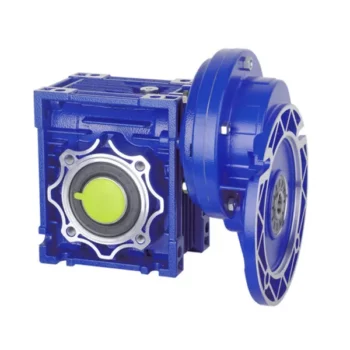
Detailed Photos
Features of S series reducer
The same model can be equipped with motors of various powers. It is easy to realize the combination and connection between various models.
The transmission efficiency is high, and the single reducer efficiency is up to 96%. three
The transmission ratio is subdivided and the range is wide. The combined model can form a large transmission ratio and low output speed.
The installation forms are various, and can be installed with any foot, B5 flange or B4 flange. The foot mounting reducer has 2 machined foot mounting planes.
Helical gear and worm gear combination, compact structure, large reduction ratio.
Installation mode: foot installation, hollow shaft installation, flange installation, torque arm installation, small flange installation.
Input mode: motor direct connection, motor belt connection or input shaft, connection flange input.
Average efficiency: reduction ratio 7.5-69.39 is 77%; 70.43-288 is 62%; The S/R combination is 57%.
S57 SF57 SA57 SAF57 S series helical worm gear box speed reducer 0.18kw 0.25kw 0.37kw 0.55kw 0.75kw 1.1kw 1.5kw 2.2kw 3kw, max. permissible torque up to 300Nm, transmission ratios from 10.78 to 196.21. Mounting mode: foot mounted, flange mounted, short flange mounted, torque arm mounted. Output shaft: CZPT shaft, hollow shaft (with key, with shrink disc and with involute spline).
Product Parameters
Company Profile
Certifications
Packaging & Shipping
FAQ
| Hardness: | Hardened Tooth Surface |
|---|---|
| Installation: | 90 Degree |
| Layout: | Expansion |
| Gear Shape: | Bevel Gear |
| Step: | Single-Step |
| Type: | Gear Reducer |
| Samples: |
US$ 100/Piece
1 Piece(Min.Order) | |
|---|
Preventing Backlash in a Worm Gearbox
Backlash in a worm gearbox can lead to reduced accuracy, positioning errors, and decreased overall efficiency. Here are steps to prevent or minimize backlash
Worm Gearboxes in Conveyor Systems: Benefits and Considerations
Worm gearboxes play a crucial role in conveyor systems, offering several benefits and considerations for their effective integration:
- Space Efficiency: Worm gearboxes have a compact design, making them suitable for applications with limited space, such as conveyor systems.
- High Reduction Ratios: Worm gearboxes can achieve high reduction ratios in a single stage, allowing for slower conveyor speeds without sacrificing torque.
- Self-Locking: Worm gearboxes have inherent self-locking properties, preventing the conveyor from moving when the motor is not actively driving it.
- Directional Control: Worm gearboxes facilitate directional control, enabling the conveyor to move forward or reverse as needed.
- Low Noise: Worm gearboxes often produce lower noise levels compared to other gearbox types, contributing to quieter conveyor operation.
However, there are also considerations to keep in mind when using worm gearboxes in conveyor systems:
- Efficiency: Worm gearboxes may have lower mechanical efficiency compared to some other gearbox types, leading to energy losses.
- Heat Generation: Worm gearboxes can generate more heat due to sliding contact between the worm and gear, necessitating proper cooling mechanisms.
- Lubrication: Proper lubrication is critical to prevent wear and ensure efficient operation. Regular maintenance is required to monitor lubrication levels.
- Load and Speed: Worm gearboxes are well-suited for applications with high torque and low to moderate speed requirements. They may not be optimal for high-speed conveyors.
Before integrating a worm gearbox into a conveyor system, it’s important to carefully consider the specific requirements of the application, including load, speed, space constraints, and efficiency needs. Consulting with gearbox experts and manufacturers can help ensure the right choice for the conveyor’s performance and longevity.
:
- High-Quality Components: Use high-quality worm gears and worm wheels with tight manufacturing tolerances. Precision components will help reduce backlash.
- Proper Meshing: Ensure the worm gear and worm wheel are properly aligned and meshed. Improper meshing can lead to increased backlash.
- Preload: Applying a small amount of preload to the worm gear can help reduce backlash. However, excessive preload can increase friction and wear.
- Anti-Backlash Mechanisms: Consider using anti-backlash mechanisms, such as spring-loaded systems or adjustable shims, to compensate for any inherent backlash.
- Lubrication: Proper lubrication can reduce friction and play a role in minimizing backlash. Use a lubricant that provides good film strength and reduces wear.
-
Calculating Gear Ratio in a Worm Reducer
The gear ratio in a worm reducer is determined by the number of teeth on the worm wheel (also known as the worm gear) and the number of threads on the worm shaft. The gear ratio formula for a worm reducer is:
Gear Ratio = Number of Teeth on Worm Wheel / Number of Threads on Worm Shaft
For example, if the worm wheel has 60 teeth and the worm shaft has a single thread, the gear ratio would be 60:1.
It’s important to note that worm reducers have an inherent self-locking property due to the angle of the worm threads. As a result, the gear ratio also affects the mechanical advantage and the system’s ability to resist backdriving.
When calculating the gear ratio, ensure that the worm reducer is properly designed and that the gear ratio aligns with the desired mechanical characteristics for your application. Additionally, consider factors such as efficiency, load capacity, and speed limitations when selecting a gear ratio for a worm reducer.
Maintenance: Regularly inspect and maintain the gearbox to identify and address any changes in backlash over time.
It’s important to strike a balance between reducing backlash and maintaining smooth operation. Consulting with gearbox experts and following manufacturer guidelines will help you optimize your worm gearbox’s performance while minimizing backlash.
editor by CX 2023-08-16
China 90 degree Gearbox NMRV030 Worm Gear Speed Reducer 51 – 80 1 for 9mm or 11mm input shaft with Great quality
Guarantee: 1 12 months
Applicable Industries: Garment Stores, Building Material Outlets, Manufacturing Plant, Machinery Mend Outlets, Meals & Beverage Manufacturing facility, Farms, Cafe, Retail, Printing Stores, Building works , Vitality & Mining, Foods & Beverage Retailers, Other
Excess weight (KG): 2 KG
Personalized support: OEM, ODM, OBM
Gearing Arrangement: Worm
Output Torque: by the ratio, by the Ratio
Input Velocity: 1400rpm, 1400rpm
Output Velocity: 14-280rpm, 14-280rpm
Rated Power: .06-15kw
Ratio: 1:10,15,twenty,25,thirty,40,fifty,sixty,eighty,100
Color: blue/silver/gray/black or CZPT your ask for
Worm equipment: 9-4# or 10-1# or 12-2#copper for your alternative
Bearing: C&U/QC or CZPT your request
Lubricant: artificial/mineral oil
Top quality Handle: ISO9001:2015
Packaging Particulars: 5 layers of Carton 063,075,090,110,130 worm gearbox

Is a worm gear reducer gearbox right for your application?
If you’re interested in gear reduction and wondering if a worm gear reducer gearbox is right for your application, you’ve come to the right place. This gear reducer gearbox is efficient and compact. In addition, it has small clearances and is easy to install. Let’s take a closer look.
This is a reducer gearbox
Worm reducer gearbox is a type of reduction gear used in machinery. This gear reduces the output speed by changing the ratio of input to output. Gears come in a wide range of sizes and can be made from a variety of materials, including aluminum, cast iron, and stainless steel. Its efficiency depends on the ratio and size of the gears. It is usually used in low speed applications. But it can also be used as an auxiliary braking device for high-speed moving machinery.
When choosing a reduction gear, it’s important to look for models with multiple teeth. Ideally, it will have more teeth than the corresponding sprocket. This will reduce the noise produced by the gears. The maximum number of teeth of the worm gear should be greater than 40.
Worm gears produce less noise and vibration than conventional gears. Also, they are cheaper and smaller than other types of reduction gears. However, worm gears have some limitations that make them less efficient than other types. For example, they do not perform as efficiently as parallel or orthogonal axes, which are much better at transmitting power.
The main disadvantage of worm gears is the difficulty of lubrication. Worm gear reducer gearboxes require more lubrication due to the helical motion of the gears. This means it is less efficient and more prone to wear than a standard gearbox. Helical motion has problems transmitting power and causes sliding friction, also known as sliding wear.
A worm reducer gearbox is a reduction gearbox used to decelerate a high-speed motor to a low-speed output. Worm gear reducer gearboxes produce lower output speeds while maintaining high torque. Its gears are made of bronze or stainless steel and have a right-angle output. The gears are very small compared to other reducer gearboxes, so they can be used in tight spaces and applications where space is limited.
Worm gear reducer gearboxes are an excellent choice for applications requiring high torque and low speeds. These reducer gearboxes are compact, durable and have a long service life. These gearboxes are also compatible with solid and hollow output shafts. This feature eliminates the need for chains or belts, reducing the number of moving parts. Plus, they’re easy to maintain, which means they’re an excellent choice for a variety of applications.
Worm gear reducer gearboxes are also compact, versatile and easy to install. The worm gear itself is made from a single piece of alloy steel. It has a high helix angle and is case hardened and ground for durability. Its six AF hex sockets are designed for easy installation and a wide range of ratios. Worm gear reducer gearboxes are also suitable for manual operation. They are easy to install, compact in design and compatible with a wide range of motors and drives.
Worm reducer gearboxes are often used in industrial settings where a small amount of torque is required to move large objects. They are also useful when space is at a premium. They are compact and easy to install in tight spaces. Worm gears reduce the risk of tripping and are often made of durable materials, making them a popular choice.
Compared with planetary gearboxes, worm gear reducer gearboxes have many advantages. They are quiet, produce less noise, and are more comfortable to use. They are also more energy efficient than their planetary counterparts. Furthermore, they can be combined with other gearboxes and trains to increase their output efficiency.
It is high efficiency
When a worm reducer gearbox is used in a gear-motor, it is critical to note that it is extremely high in efficiency. This type of reducer gearbox is typically much hotter than a hypoid reducer gearbox, which reduces the service life of the gear. The increased thermal stress on the sliding gears results in premature seal wear and leakage. Furthermore, excessive heat causes lubrication to break down and can cause contamination. Helical gear reducer gearboxes are significantly cooler and have a low-maintenance design. Consequently, they can reduce factory downtime and energy costs.
A servo-worm reducer gearbox is an excellent choice for applications requiring high performance, repeatability, and precision positioning. These gear reducer gearboxes have been specifically designed for use with servo motor technology, which provides tight integration of the gear motor. Other advantages of a servo-worm reducer gearbox include reduced angular backlash and longer life.
Hypoid gearmotors offer increased efficiency and allow smaller motors to be used. A 1 HP worm reducer gearbox can produce the same amount of output as a 1/2 HP hypoid reducer gearbox. A Agknx study compared the two types of reducer gearboxes, comparing power, torque, and efficiency. As a result, a 1/2 HP hypoid gearmotor is much cheaper to operate than a 1 HP worm reducer gearbox.
The efficiency of a worm gear reducer gearbox depends on many factors, including the mesh of the gears and losses in the bearings and oil seal lips. The speed and load of the reducer gearbox also have an impact on its efficiency. As a result, worm gear reducer gearboxes should be used with the right type of lubricant.
In a worm gear reducer gearbox, a non-intersecting shaft rotates against a gear, while the output worm gear rotates in a perpendicular direction. This arrangement produces high efficiency while reducing the noise and vibration of the gear motor. This gear reducer gearbox is also quiet and has a low friction coefficient.
It has a low clearance
Worm reducer gearboxes are typically designed with a low clearance, meaning that the worm is not allowed to touch the wheels in the gear arrangement. The lubricant used depends on the size of the gearing, and it is usually ISO 680 or ISO 460. Higher viscosities require special equipment.
Worm gears are popular in machines that need to stop quickly, such as lifts and elevators. The gears and worm are made of a soft material, minimizing backlash and failure rates. They are also popular in heavy-duty machines, such as rock crushers. But while this is an important aspect of their design, there are other factors to consider when choosing a worm gear.
Worm gears have multiple teeth, which allows for greater surface area contact and a better distribution of load. This feature allows for high transmission ratios without sacrificing power. Worm gears can be paired with other gearboxes to increase the overall efficiency of the system.
Worm gears are often used in heavy machinery, including trucks barreling down a deserted highway. They can also be found in packaging machinery, conveyors, and other small machinery. Their unique shape makes them ideal for tight spaces. But they also tend to wear and tear much faster than conventional gears.
It has a high torque to weight ratio
The worm gear reducer gearbox is a versatile gear train that provides a high torque-to-weight ratio. These reducer gearboxes are typically used in applications that require high torque and high gear ratios, such as machine tools. They also have a very compact design, enabling very high gear ratios at low speeds.
Worm gear reducer gearboxes are very quiet, mainly because the input and output shafts are perpendicular to each other. Their low noise level is an advantage compared to planetary gearboxes. Compared with planetary reducer gearboxes, worm gear reducer gearboxes are also relatively cheap.
The worm gear consists of two parts: the helical butt-jointed worm gear and the worm. The screw-butted worm gear is connected to the shaft by a helical thread. The worm gear is a variation of the six-simple machine. The worm is located in the worm wheel, which forces the worm to rotate. It also changes the plane of motion. Worm gears are usually made of steel or brass.
Worm gear reducer gearboxes are one of the most popular types of reducer gearboxes. It provides high torque and high speed ratio in a compact package. These reducer gearboxes are used in many power transmission systems, including elevators, safety gates, conveyor belts, and medical testing equipment.
Worm reducer gearboxes come in a variety of shapes and sizes, including parallel shaft reducer gearboxes and planetary worm reducer gearboxes. They have a high torque-to-weight ratio and are easy to maintain. They are also lightweight and relatively easy to install. This makes them an excellent choice for many applications.
Worms can be assembled using stepped shafts, set screws or dowel pins. However, the worm is subject to a lot of thrust and must be held firmly. This could lead to a rebound. Also, the bearings may come loose and the worm may move. To avoid backlash, make sure the worm gear shaft passes through the midpoint of the worm face width.
editor by Cx 2023-06-27